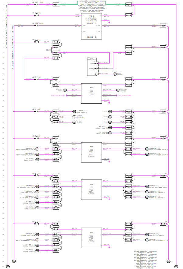
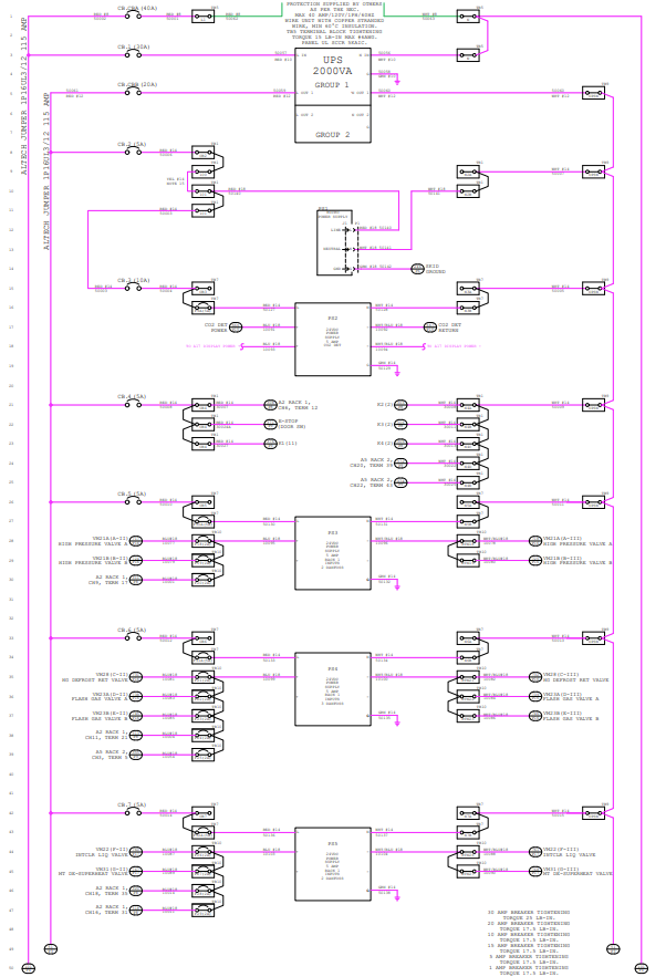
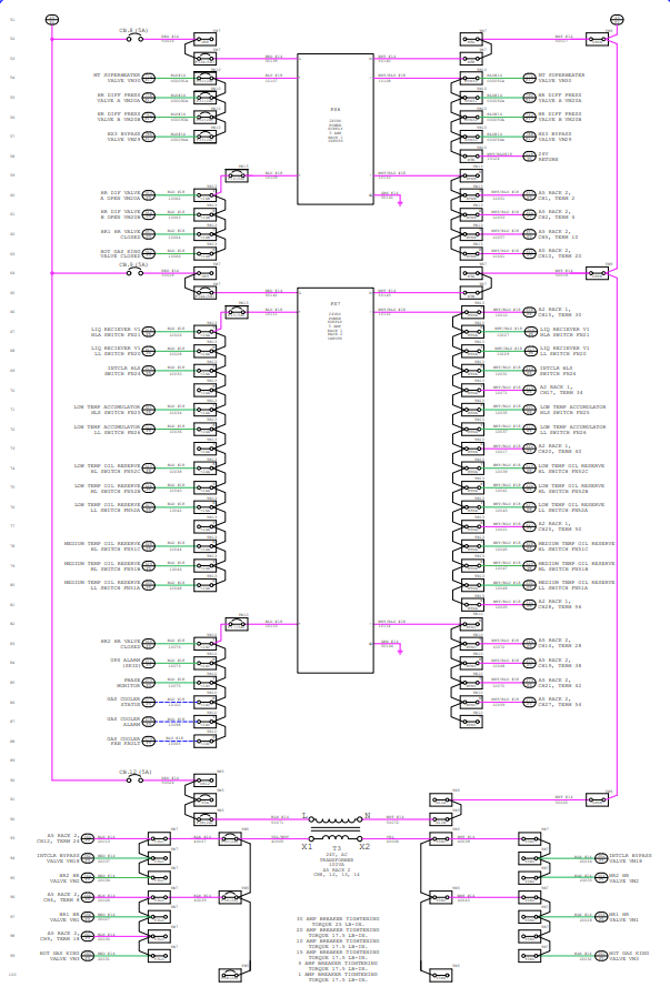
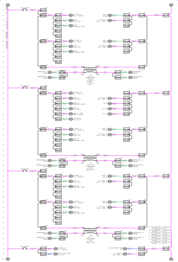
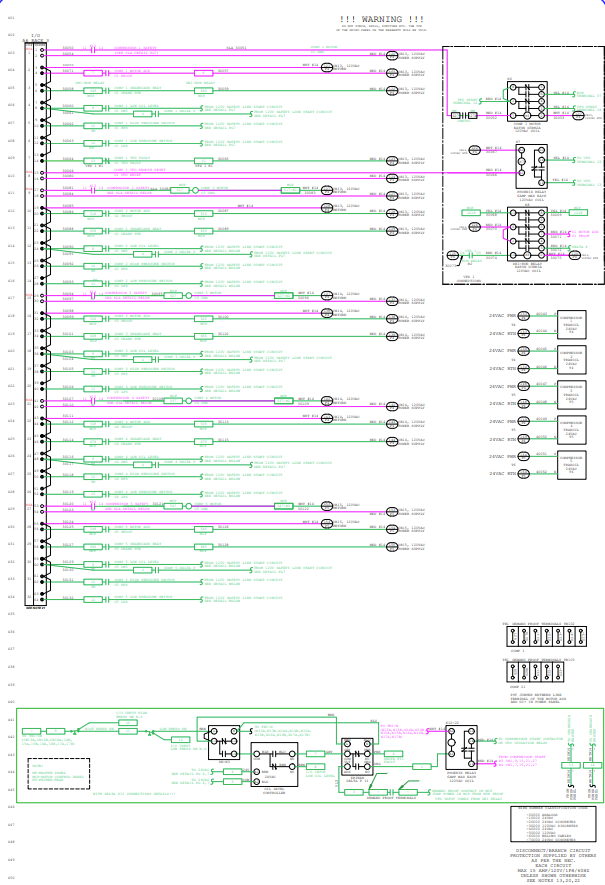
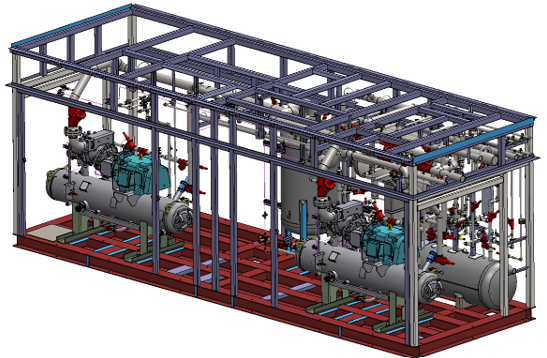
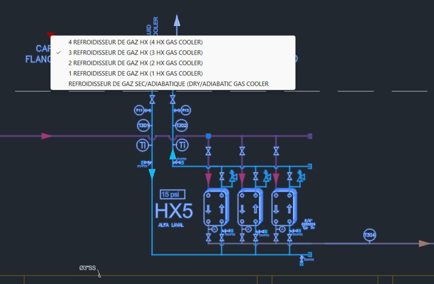
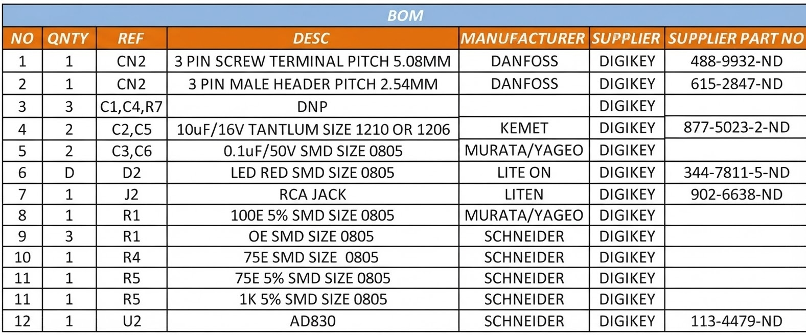
The client required control drawings to guide the manufacturing and installation of a CO2 refrigeration system. Rather than simply recreating the client's existing documentation, our electrical engineering team identified an opportunity to improve the drawings' usability for the technicians who would rely on them during assembly and troubleshooting.
The original diagram used segmented, floating elements with minimal visual connection between components, increasing the time and effort needed to interpret the drawing on the shop floor.
The engineering requirement was to remap the control drawing using ladder logic — organizing all related components in a clear, connected sequence — and to structure the layout around the system's actual power flow: from power source, to main controller, to the slave devices the controller manages. The goal was documentation that mirrored real-world wiring and control logic, reducing clutter and making the drawing intuitive for both engineers and shop-floor technicians.