
Explore our advanced solutions for HVAC, Mechanical, Electrical, and Automation design. Get in touch today

Precision Tooling & Surface Finish

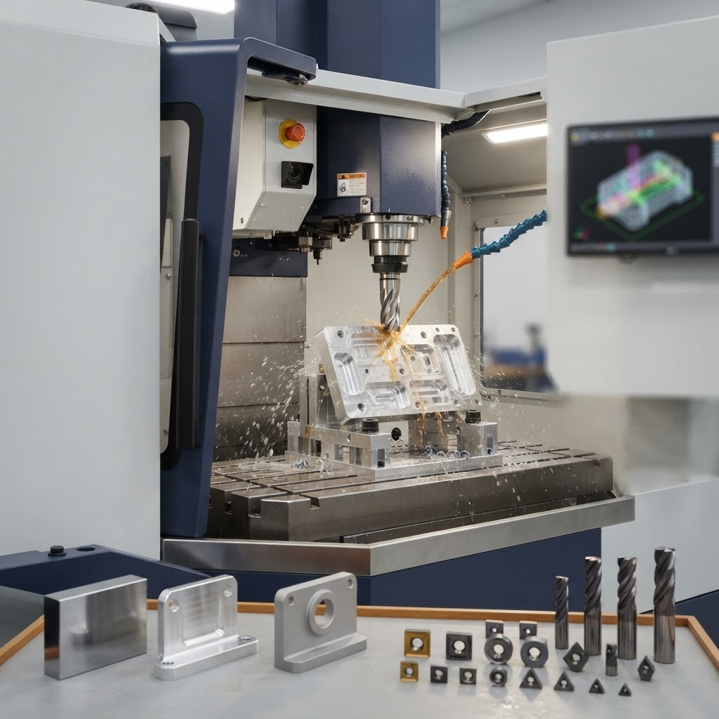
Custom insert cutter design, reamer setups, and strict GD&T analysis aligned with ASME Y14.5 and B46.1 standards.

Specialized Engineering Services

GD&T Analysis & Tolerance Interpretation

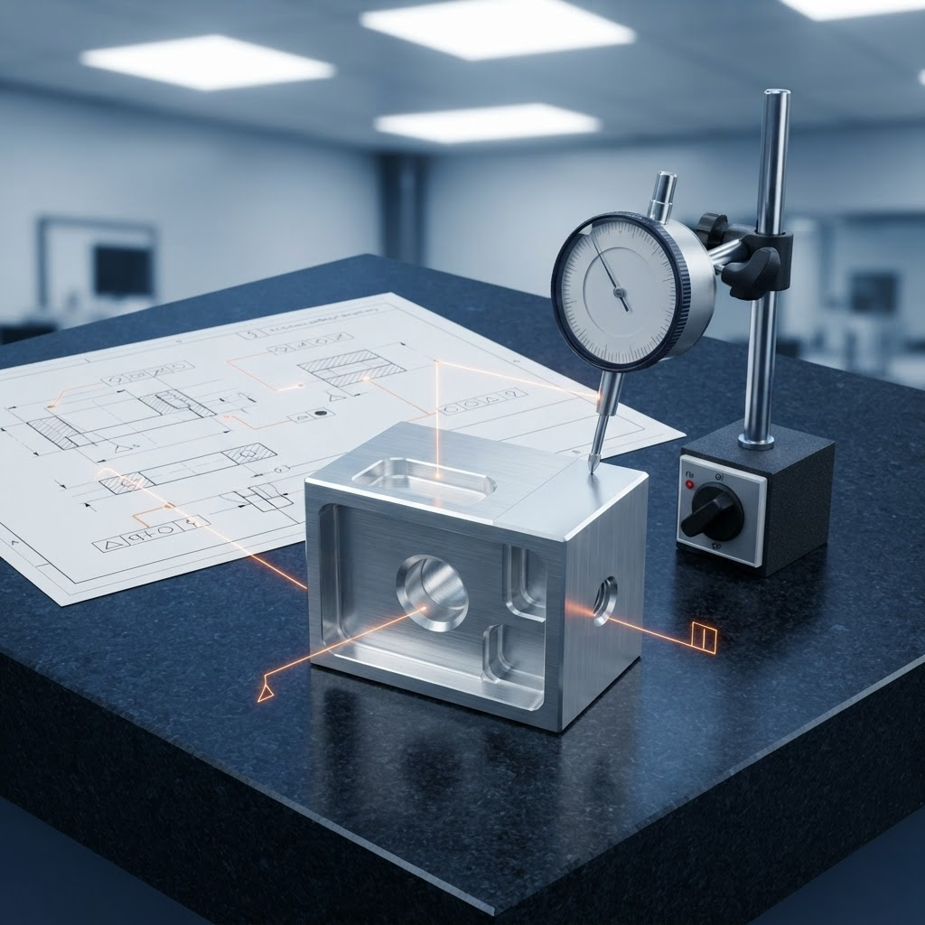
GD&T analysis and tolerance interpretation is the process of translating drawing-level geometric dimensioning and tolerancing requirements into concrete tooling design parameters. Asset-Eyes performs this analysis per ASME Y14.5, ensuring every tooling and fixture decision traces back to a specific drawing requirement rather than a general assumption.
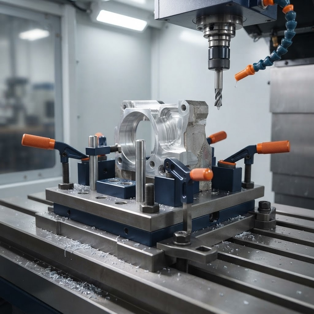
GD&T-to-Tooling Traceability
Asset-Eyes performs GD&T analysis per ASME Y14.5, establishing traceable links between drawing requirements and tooling design parameters, and formalizes these links into a GD&T-to-tooling traceability matrix. This matrix connects each drawing requirement directly to the machining process responsible for meeting it. Asset-Eyes uses this traceability to keep tooling decisions auditable back to the original print.
Surface Texture Analysis
Asset-Eyes conducts surface texture analysis, including Ra, Rz, Rmax, and bearing ratio curve evaluation, to validate functional surface performance. This analysis confirms that a machined surface will perform as intended in its application, not just meet a numeric roughness target. Asset-Eyes applies these metrics to define finishing requirements before tooling is selected.
Form Tolerance Translation
Asset-Eyes translates form tolerances, including flatness, cylindricity, and circularity, into concrete tooling stiffness, runout, and setup requirements. This step converts an abstract print tolerance into specific, actionable machine and tooling parameters. Asset-Eyes uses this translation to determine what tooling rigidity and setup precision a given form tolerance actually demands.
Position and Profile Tolerance Interpretation
Asset-Eyes interprets position and profile tolerances to drive fixture design and toolpath strategy development. This interpretation determines how a part must be located and machined to consistently meet its positional requirements. Asset-Eyes builds fixture and toolpath decisions directly from this interpretation rather than from general machining practice.
GD&T Analysis & Tolerance Interpretation

Tooling & Fixture Design

Tooling and fixture design covers the engineering of complete tool assemblies and specialized cutting tools built to meet the tolerance and surface finish requirements identified during GD&T analysis. Asset-Eyes designs these tools and assemblies from the ground up, integrating cutting tools, holders, fixtures, and support systems into a single coordinated system.

Complete Tooling Assembly Design
Asset-Eyes designs complete tooling assemblies that integrate cutting tools, holders, fixtures, and support systems into a single functional system. This ensures every component of the assembly works together toward the same tolerance and finish targets. Asset-Eyes engineers these assemblies as a coordinated system rather than a set of independently sourced parts.
Custom Insert Cutter Configuration
Asset-Eyes develops custom insert cutter configurations with optimized pocket geometry, seating repeatability, runout control, and coolant delivery. This configuration work is tailored to the specific material and finish requirements of the part being machined. Asset-Eyes designs these cutters to maintain consistent performance across repeated production runs.
Precision Reamer Design
Asset-Eyes designs precision reamers with optimized land geometry, flute configuration, chip evacuation, and coolant delivery systems. These design choices directly affect hole finish quality and dimensional consistency in reaming operations. Asset-Eyes engineers each reamer to the specific bore tolerance and material requirements of the application.
Specialized Finishing Tool Development
Asset-Eyes develops specialized finishing tools, including burnishing, honing, and form tooling, for applications requiring ultra-fine surface finishes. This tooling addresses surface requirements that standard cutting tools cannot reliably achieve. Asset-Eyes selects and designs the finishing method based on the surface texture targets identified during GD&T analysis.
Tooling & Fixture Design

Machining Process Engineering

Machining process engineering covers the analysis and parameter development that ensures a machining process consistently produces parts within tolerance across multiple operations and materials. Asset-Eyes engineers these processes around real-world factors like tooling runout, thermal expansion, and material behavior, rather than relying on generic machining parameters.

Tolerance Stack Analysis
Asset-Eyes performs tolerance stack analysis across multi-stage machining operations, accounting for tooling runout, fixture positioning, and thermal expansion effects. This analysis identifies how small deviations at each stage compound across a multi-step process. Asset-Eyes uses this analysis to catch tolerance risks before they show up as out-of-spec parts on the final operation.
Face Milling Process Engineering
Asset-Eyes engineers face milling processes for critical sealing surfaces, targeting high flatness and superior surface finish requirements. This process engineering is applied specifically where the machined surface must perform a sealing function. Asset-Eyes tunes the milling process to meet both the flatness and finish requirements simultaneously.
Material-Specific Machining Strategies
Asset-Eyes develops material-specific machining strategies for hardened steels, stainless steels, aluminium alloys, and CFRP composites. Each material behaves differently under cutting forces and heat, so Asset-Eyes adjusts strategy accordingly rather than applying a single generic approach. Asset-Eyes builds these strategies around the specific tooling and finish requirements tied to each material.
Cutting Parameter Engineering
Asset-Eyes engineers and validates cutting parameters, including speed, feed, depth of cut, and coolant delivery, for consistent surface quality. This validation confirms the parameters actually produce the required finish and tolerance in practice, not just on paper. Asset-Eyes ties these parameters directly to the material strategy and tooling design already established.
Machining Process Engineering

Documentation & Production Standardization

Documentation and production standardization covers the manufacturing paperwork and process controls that let a tooling design move into repeatable production. Asset-Eyes produces this documentation directly from the finalized tooling and process engineering work, so production teams have a single, traceable reference for setup and execution.

3D Tooling Assembly and GD&T-Compliant Documentation
Asset-Eyes produces manufacturing documentation including 3D tooling assemblies and GD&T-compliant drawings that reflect the finalized tooling design. This documentation gives production teams an accurate, dimensionally correct reference for building and inspecting the tooling. Asset-Eyes builds these drawings directly from the same GD&T analysis used to design the tooling.
Traceability Matrices and Process Sheets
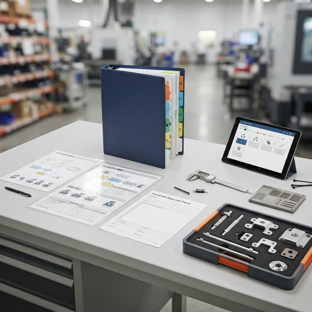
Asset-Eyes develops traceability matrices and process sheets as part of its manufacturing documentation, linking each production step back to the original drawing requirement. This keeps the connection between print requirements and shop-floor execution intact throughout production. Asset-Eyes structures these documents so any step in the process can be traced back to its source requirement.
Production Setup Optimization
Asset-Eyes optimizes production setup through integrated tooling documentation and process standardization. This reduces setup variability between production runs and operators. Asset-Eyes builds this standardization directly on top of the tooling assemblies, drawings, and process sheets already developed for the project.
Documentation & Production Standardization
Engineering Tools

Machine Design Engineered To Perform

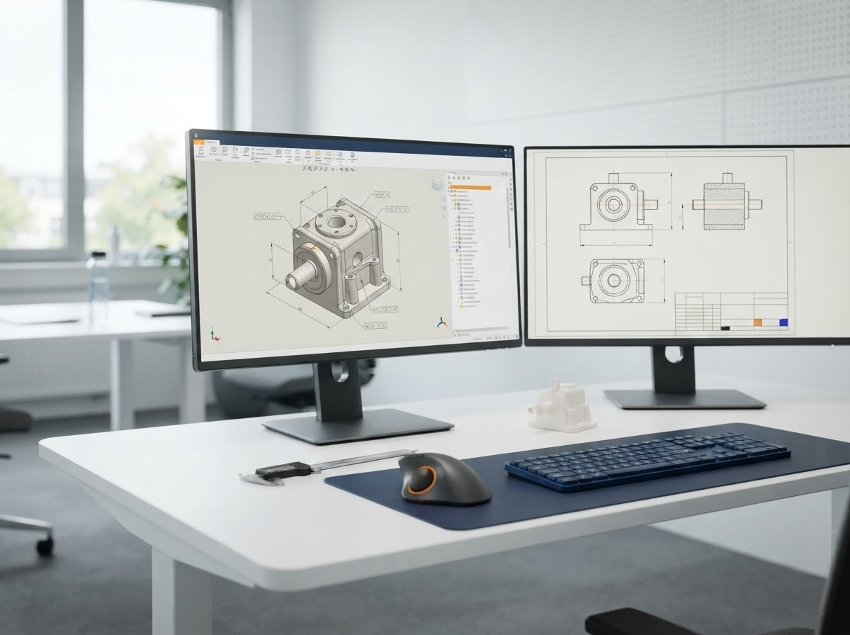
Automation machine design is exclusively a 3D process at Asset-Eyes. We utilize industry-leading CAD environments to guarantee compatibility and seamless translation to the factory floor.
Engineering Tools
1

SOLIDWORKS

SOLIDWORKS is used to develop mechatronics systems from beginning to end. At the initial stage, the software is used for planning, visual ideation, modeling, feasibility assessment, prototyping, and project management. The 3D modeling software is then used for design and building of mechanical, electrical, and software elements.
2

AutoCAD

AutoCAD is our primary design tool for controls engineering (electrical, fluid power) and the latest software versions are always utilized. We use the AutoCAD Electrical Toolset for the creation of controls drawings. The use of AutoCAD Electrical Toolset improves efficiency, reduces errors, and essentially creates a smart design package.
3

Additional Software Competence

For manufacturers standardizing on alternative platforms, our team maintains full functional design workflows in Autodesk Inventor and PTC Creo Parametric, ensuring full design history, parametric constraints, and drawing format compliance.

Resources

Let's Talk About Your Engineering Needs

Tell us where your team needs more capacity. We'll show you how our engineers can help.